
1st Semester Notes for B.tech
Basic Electrical Engineering: notes for module 1 | DC Network
 |
| DC Network| part 1 |
These notes will be covered by the following topics:
- Ohm's Law
- Kirchhoff's Law
- Current/Voltage divider rule
- Network Theorem
- Maximum power transfer theorem
- Time-domain analysis of first-order RL and RC circuits
1. Ohm's Law
According to Ohm's law, the Potential Difference (v) across the end of the conductor is directly proportional to the Current(I) following through the conductor.
V α I
V=IR
where R is proportionality constant and known as resistance. Its SI unit is Ω.
Graphically, V-I relation for Resistor

The ratio of voltage/Current is always constant.
2. Kirchhoff's Law
Kirchhoff's law is the generalized form of Ohm's law and the concept of conservation of charge and conservation of energy.
(i). Kirchhoff's Voltage Law:
According to Kirchhoff's Voltage Law(KVL), the algebraic sum of all the electromotive force(emf) and voltage(V) drops will be zero in any closed circuit. It is also known as Kirchhoff's Second Law or Kirchhoff's Mesh/Loop Rule.
Σemf + ΣIR = 0
To solve KVL problems, we use the Mesh analysis method.
Mesh Analysis Method: The mesh analysis method is the closed path through which electricity can flow but that closed path shouldn't contain any closed path.

The number of Mesh in the figure is 3.
Loop Analysis Method: The loop analysis method is the closed path through which electricity can flow and it can contain various other closed-loop.
(ii). Kirchhoff's Current Law:
According to Kirchhoff's Current Law(KCL), the algebraic sum of the currents meeting at a junction will be zero. It is also known as Kirchhoff's First Law and Kirchhoff's Nodal/Junction Rule.
Σcurrent in = Σcurrent out

- Why do we need Kirchhoff's Law, if Ohm's Law is given?
Q. What is the basic concept of Voltage Drop and Voltage Rise?
A. Voltage drops when the current flows from a lower potential to a higher potential. It is also known as Drop-in-Potential.
Voltage rise when the current flows from a higher potential to a lower potential. It is also known as Rise-in-Potential.

 |
| Mesh, Loop, Node, and Branch in one circuit |
3. Voltage and Current divider rule:
(i). Voltage Divider rule:
Voltage Divider Rule is used to finding the voltage across a resistor R. Resistor should be in series.
 |
Voltage Divider rule |
we know that I=V/Req
VR1= R1.I
=R1.V/Req
VR1= R1/(R1+R2+R3). V
Req= R1+R2+R3
(ii). Current Divider Rule:
Current Divider Rule is used to finding the current across a resistor R. Resistor should be in parallel.
 |
Current Divider Rule |
we know that V=I.Req
for parallel, Req = 1/(1/R1+1/R2+1/R3)
IR1 = V/R1 = Req . I/R1
4. Network Theorem
It can be classified in three terms:
- Superposition Theorem
- Thevenin's Theorem
- Norton's Theorem
(i). Superposition Theorem:
According to the superposition theorem, The current or voltage across any branch in any linear or bilateral multisource circuit is the algebraic sum of current or voltages due to each source acting alone, all other sources will be removed at that time.
- It isn't applied for single-source circuit or non-linear circuit
- It doesn't work for power calculation as power calculations involve either the product of current and voltage, the square of current and voltage isn't a linear operation.
- We have to analyze networks in the circuit such that, it has two or more source which is in parallel or in series.
- Then identify the source, whether it is an ac or dc source. now separate circuit with one source and remove other sources
- The result will be the algebraic sum of each source calculated separately.
`

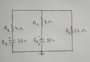
Sol. Taking 16V source and replacing other active sources with internal resistance
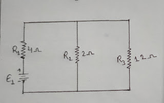
R= 4 Ω + (2×12)/(2+12) Ω
= 5.71 Ω
From Ohm's law,
I = E1/R
= 16/5.71 A= 2.8A
Using Current Divider Rule, we get
I1= I×R2/(R2+R3)
= (2.8×2)/(2+12) A
= 0.4 A
So, Current through the 12 Ω resistor is 0.4A
Taking 10V source and replacing all other active sources with internal resistance
R= 2 Ω + (4×12)/(4+12) Ω
= 5 Ω
From Ohm's law,
I = E2/R
= 10/5 A= 2 A
Using Current Divider Rule, we get
I2= -I×R1/(R1+R3)
= (-2×4)/(4+12) A
= -0.5 A
So, Current through the 12 Ω resistor is -0.5
The total current through 12Ω resistor is
IT = I1+I2 = (0.4-0.5) A = -0.1 A
Therefore, current rise 0.1 A through 12 Ω
(ii). Thevenin's Theorem:
According to Thevenin's Theorem, any linear circuit (two-terminal) of DC Network consisting of resistors and sources, can be replaced by an equivalent circuit.
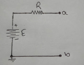 |
| Thevenin's Equivalent Circuit |
- It consists of Thevenin's open-circuit voltage "VTH" in series with Thevenin's equivalent resistance "RTH" along with load resistor.
- The current "IL" through the load resistance "RL" is the same.
- We have to analyze networks in the circuit with the source which is in parallel or in series.
- Identify the load resistor RL
- Then remove RL and calculate the open circuit, potential across two open ends. This will be Thevenin's equivalent voltage VTH.
- Again remove RL and replace other active sources with internal resistance.
- Calculate the Thevenin's equivalent resistance "RTH"
- Draw the Thevenin's equivalent circuit for the given network
- calculate the load current IL by using
Q. Find the Thevenin's Equivalent Circuit for the network external to the resistor R for the network when the load resistor is 2kΩ and 100kΩ
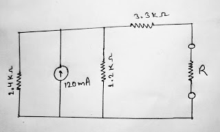
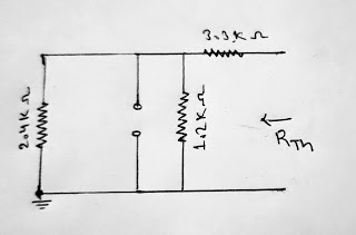
RTH = 3.3 Ω +(1.2×2.4)/(1.2+2.4) Ω
= 4.1kΩ
To find VTH, no current flows through 3.3k Ω resistor
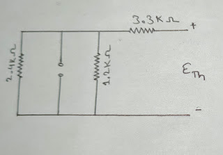
Applying Kirchhoff's Current Law (KCL) to an upper node,
120 mA= ETH/0.8 kΩ
ETH= 96V
Thevenin's Equivalent Circuit,
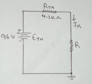
For Thevenin's Circuit,
IR= ETH/ (RTH+RL)
When R= 2kΩ
IR= 96 V/(4.1+2) kΩ = 15.74mA
When R= 100kΩ
IR= 96 V/(4.1+100) kΩ = 922.2 μA
(iii). Norton's Theorem:
Norton's Theorem states that any linear circuit of DC Network consisting of resistors and sources can be replaced by a single constant current generator in parallel with a single resistor.
Norton's Equivalent Circuit consists of:
- Norton's Short Circuit Current (IN)
- Norton's Equivalent Resistance (RN)
- Load resistor (RL)
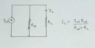
IL = RN.IN/(RN+RL)
Norton's Theorem is dual of Thevenin's Theorem and both are related by equations:
RTH = RN
VTH = RN.IN
IN = RTH/VTH
To solve question via Norton's Theorem:
- Identify the load resistor RL.
- Then remove RL and replacing other voltage sources with a short circuit.
- Current flowing through a short circuit branch will be Norton's Current(IN)
- Remove RL and replace all other sources with internal resistance
- The equivalent resistance across the two open ends will be Norton's resistance(RN)
- Draw Norton's equivalent circuit for the given network
- calculate the load current IL by using
IL= RN.IN/(RN+RL)
Q. Find the Norton's Equivalent Circuit for the network external to the resistor R?

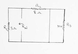
RN = 3×8/(3+8) = 2.1 Ω
Finding IN

Applying Ohm's Law to the two resistors (3Ω & 8Ω)
I8Ω= 12/8 A= 1.5 A
I3Ω= 18/3 A= 6 A
Applying Kirchhoff's Current Law(KCL) to a node,
IN = I3Ω - I8Ω
= 6 A - 1.5 A
= 4.5 A
Norton's Equivalent Circuit,

5. Maximum Power Transfer theorem
According to the Maximum Power Transfer Theorem, to obtain maximum external power from a source with finite internal resistance, the load resistor RL must be equal to the resistance of the source as viewed from its output terminals.
Derivation of maximum, Power transfer Theorem:
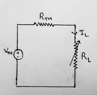 |
| RL is a variable because we want to gain maximum power RL=RTH |
Power through the load resistor, RL
P= IL² . RL ----- (i)
IL = VTH/ (RTH + RL)
By putting the value of IL in equation 1, we get
P= (VTH/ (RTH + RL))² . RL -------(ii)
On differentiating the equation (ii) w.r.t RL and equating it with zero, we get
dP/dRL = Vm² [ {(RTH + RL)² - 2 (RTH + RL) . RL}/ (RTH + RL)² ]
= 0
RTH² - RL² = 0
Therefore, RTH = RL --------(iii)
This is the required condition for max power flow.
Putting the value of RTH = RL in the equation (ii), we get
Pmax = VTH² . RTH/ (RTH +RTH)²
= VTH²/4RTH
Q. In the given circuit, Find the value of RL which will absorb the maximum power from the source. Also, find the maximum power.
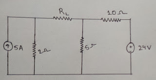
Applying Kirchhoff's Voltage Law,
In mesh 2,
-15I2 = 24
I2 = -1.6 A
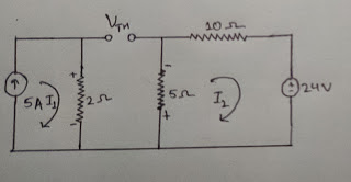
Converting AB short circuit into voltage circuit :
V = I2.5Ω = -8 V
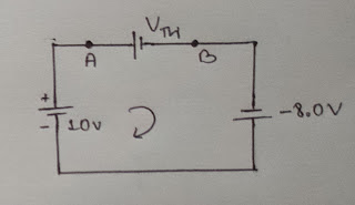
-VTH - 8 + 10 = 0
VTH = 2V
Removing RL and replacing all active sources with internal resistance,
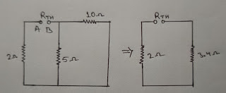

RTH = 5.4Ω
Therefore, RL = RTH = 5.4Ω ----------- For maximum Power flow
Pmax = VTH²/4RTH
= 2²/4(5.4) = 0.19W
6. Time Domain Analysis of First-order RL and RC circuit
Time Domain Analysis is also known as Transient Analysis. It consists of Resistance(R), Inductor(L), Capacitor(C) with a voltage source, current source, and switches.
Analyzing the response of a circuit with sudden application of current/voltage is known as Time Domain Analysis.
Elements of circuits like Resistance(R), Inductor(L), and Capacitor(C) are very strong and can absorb any disturbance.
The natural response of RL and RC circuit is for source free circuit
(i) Time-domain analysis of RL circuit
Current doesn't reach its maximum value instantaneously due to disturbance created due to presence of Inductor(L). Therefore, it increases gradually and takes time to reach its maximum position.
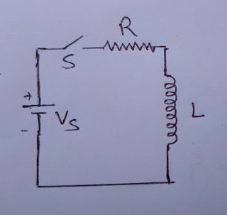
Applying Kirchhoff's Voltage Law(KVL),
iR + L di/dt = V
di/V-iR = dt/L
-R di/V-iR = -R dt/L ----------(Multiplying both side R)
By integrating both side,
loge(V-iR) = -Rt/L +C
when i=0, t=0
loge(V-0) = 0+C
C = logeV
∴ loge(V-iR) = -Rt/L + logeV
(V-iR)/V = e-(R/L).t
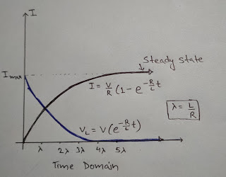
i=V/R(1-e-(R/L).t)
Now,
at t=0
i= V/R (1-e⁰) = 0
at t=
I= V/R (1- e-1) = 0.632 V/R
Graph of Time Domain Analysis of First-Order RL circuit
(ii) Time Domain Analysis of RC circuit
An RC circuit is connected with a switch in series. When the switch is closed, there is no charge in the capacitor whereas when we close the switched capacitor starts charging, and the potential difference(V) increases gradually.
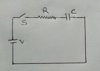
During Charging
Vc= voltage across capacitor i= Charging Current
q= Charge
i=dq/dt = d(CVc)/dt ------(i)
According to Kirchhoff's Voltage Law(KVL),
V= iR + Vc
V - Vc = RC dVc/dt ------- From equation (i)
dVc/V-Vc = dt/RC
By integrating both side,
loge(V-Vc) =-t/RC + K
when t=0, Vc=0
loge(V-0) = 0 + K
k= logeV
∴ loge(V-Vc) =-t/RC + logeV
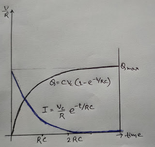
Vc = V(1-e-t/RC)
Now,
at t=0
Vc = V (1-e⁰) = 0
at t=
Vc = V(1- e-1) = 0.632 V
When t>>RC ,
Vc = V (fully charged capacitor)
Graph of Time Domain Analysis of First-Order RL circuit
Here we completed full notes of Module 1 or DC Network
We will update more notes on this website
keep visiting


This is really a good source of information, I will often follow it to know more information and expand my knowledge, I think everyone should know it, thanks Best Thermal Imaging Dandenong service provider.
ReplyDelete